
| p | ~p |
| 1 | 0 |
| 0 | 1 |

| p | q | (p ∧ q) |
| 1 | 1 | 1 |
| 1 | 0 | 0 |
| 0 | 1 | 0 |
| 0 | 0 | 0 |

| p | q | (p ∨ q) |
| 1 | 1 | 1 |
| 1 | 0 | 1 |
| 0 | 1 | 1 |
| 0 | 0 | 0 |
The not gate takes one input and inverts it (an input of 1 is changed to a 0; an input of 0 is changed to a 1). The basic AND gate takes two inputs and produces an output of 1 if and only if both inputs are 1. More generally an AND gate can take any number of inputs and produce an output of 1 if and only if all the inputs are 1. The OR gate takes two inputs and produces an output of 1 if and only if one or both of the inputs is 1 (the output is 0 only when both inputs are 0). More generally an OR gate takes n inputs and produces an output of 0 if and only if all inputs are 0. Note that each gate corresponds to a logic statement (where we think of 1 as T and 0 as F). For each gate we have a symbol representing the gate and summarize the output in a truth table.
| Gate | Symbol | Logic Statement | Truth Table | |||||||||||||||
| NOT | |
~p |
|
|||||||||||||||
| AND | |
p∧q |
|
|||||||||||||||
| OR | |
p∨q |
|
More complicated logic circuits are constructed by concatenating these basic gates. Just as basic gates have corresponding logic statements so do more complicated circuits. The behavior of the circuits can be summarized in a truth table that shows the output for each possible combination of inputs.
Examples: For each of the following circuits, write the corresponding logic statement and construct a truth table showing the outputs. (Note: The truth table can be constructed in one of two ways. One way is to use the statement and construct the table for it. The other way is to trace 1's and 0's through the circuit. Usually the statement method is faster.)
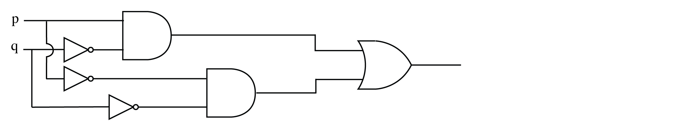
1.

To find the statement corresponding to this logic circuit it is usually easiest to trace through from the inputs writing the statement coming out of each gate.

TRUTH TABLE:
| p | q | p ∨ ~q | ~(p ∨ ~q) | ~(p ∨ ~q)∨p | ~(~(p ∨ ~q) ∨ p) |
| 1 | 1 | 1 | 0 | 1 | 0 |
| 1 | 0 | 1 | 0 | 1 | 0 |
| 0 | 1 | 0 | 1 | 1 | 0 |
| 0 | 0 | 1 | 0 | 0 | 1 |
2.

TRUTH TABLE:
| p | q | r | q ∧ ~r | ~p ∧ (q ∧ ~r) | ~(~p ∧ (q ∧ ~r)) |
| 1 | 1 | 1 | 0 | 0 | 1 |
| 1 | 1 | 0 | 1 | 0 | 1 |
| 1 | 0 | 1 | 0 | 0 | 1 |
| 1 | 0 | 0 | 0 | 0 | 1 |
| 0 | 1 | 1 | 0 | 0 | 1 |
| 0 | 1 | 0 | 1 | 1 | 0 |
| 0 | 0 | 1 | 0 | 0 | 1 |
| 0 | 0 | 0 | 0 | 0 | 1 |
Simplifying Circuits Two circuits that produce the same output for the same input are logically equivalent. One method of determining a simpler circuit than a given one is to use the laws of logic to simplify the logic statement and then construct a circuit corresponding to the simpler statement. The goal is to minimize the number of gates in the circuit.
Example Find simpler but equivalent circuits to the two examples above.
1. We first use the laws of logic to simplify the statement (found above).
| ~(~(p ∨ ~q) ∨ p) ≡ (p ∨ ~q) ∧ ~p | (Use DeMorgan's law and the double negative) |
| ≡ ~p ∧ (p ∨ ~q) | (Commutative law -- just change the order) |
| ≡ (~p ∧ q) ∨ (~p ∧ ~q) | (Distributive law) |
| ≡ F ∨ (~p ∧ ~q) | (p and not p is a contradiction) |
| ≡ ~p ∧ ~q | (contradiction OR a statement is equivalent to the statement) |
| ≡ ~(p ∨ q) | (DeMorgan's law --- "in reverse") |
The circuit corresponding to this simpler statement is:

2.
| ~(~p ∧ (q ∧ ~r)) ≡ p ∨ ~(q ∧ ~r) | (DeMorgan's law and double negative) |
| ≡ p ∨ (~q ∨ r) | (DeMorgan's law and double negative) |
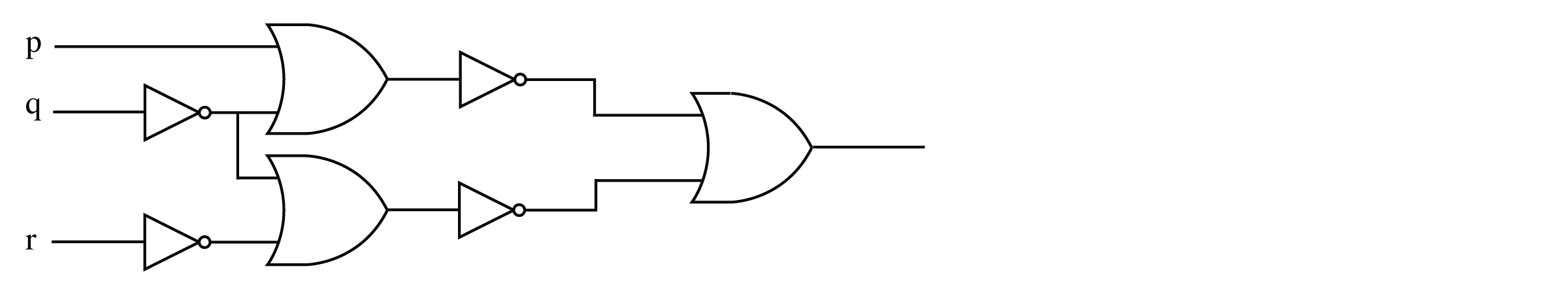
We can draw this using two or gates and a not gate

or using one three-input or gate and a not gate:

Designing Logic Circuits Suppose you are given a truth table and you want to design a logic circuit that will have exactly that truth table. What is the best way to go about it? In some simple cases you can tell immediately from the truth table. Suppose we have the following truth table.
| p | q | Output |
| 1 | 1 | 0 |
| 1 | 0 | 1 |
| 0 | 1 | 0 |
| 0 | 0 | 0 |
We recognize this as the table for p and not q (the output is 1 only when both p and not q are 1) so the circuit would be...

For more complex truth tables it is easiest to design the circuit as a disjunction of simpler circuits called recognizers. A recognizer is a circuit that outputs a 1 for exactly one particular combination of inputs (for all others it outputs a 0). The example above is a recognizer because it outputs a 1 only when p is 1 and q is 0. To design a circuit for the following truth table,
| p | q | Output |
| 1 | 1 | 1 |
| 1 | 0 | 0 |
| 0 | 1 | 0 |
| 0 | 0 | 1 |
we construct a recognizer for each case in the table where the output is 1. The statement p ∧ q has output 1 only when p is 1 and q is 1. This is the recognizer for the 1 in the first row of the truth table. The statement ~p ∧ ~q has output 1 only when p is 0 and q is 0 hence is the recognizer for the 1 in the last row of the truth table. We connect these recognizers with ∨ to get a statement that has 1's exactly in rows 1 and 4 of the truth table. We can check that this is correct by constructing the truth table.
| p | q | p ∨ q | ~p ∨ ~q | (p ∧ q) ∨ (~p ∧ ~q) |
| 1 | 1 | 1 | 0 | 1 |
| 1 | 0 | 0 | 0 | 0 |
| 0 | 1 | 0 | 0 | 0 |
| 0 | 0 | 0 | 1 | 1 |
Hence the logic circuit for the truth table is the circuit corresponding to the statement (p ∧ q) ∨ (~p ∧ ~q):
Example Suppose we want to design a logic circuit to test to see if two bits are equal. The circuit should have two inputs and output a 1 when the two inputs are equal; otherwise output a 0. We note that the truth table for this circuit is exactly the same as in the example above hence that circuit is the solution --- it tests for equality of its two input bits.
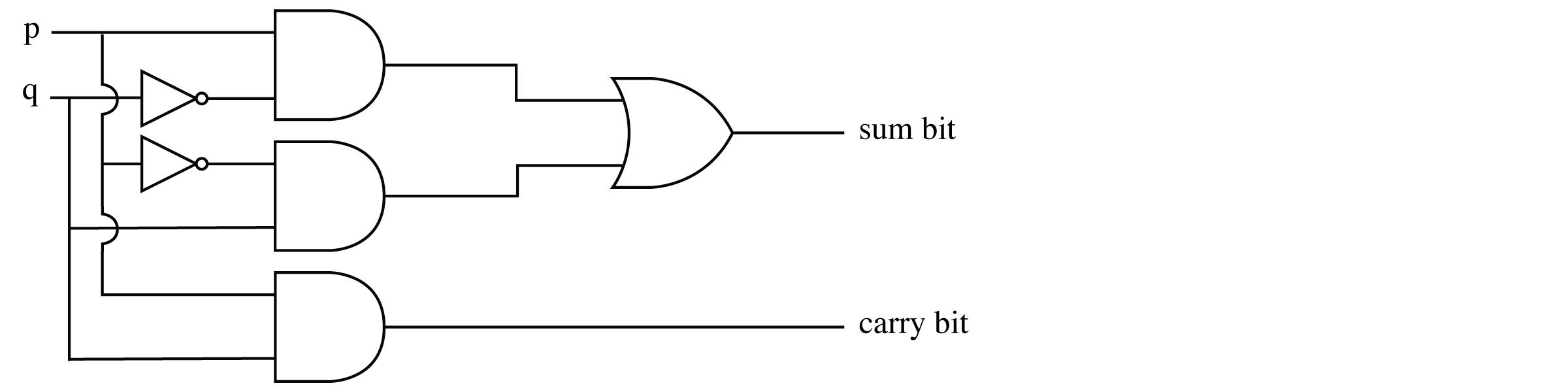
Example Suppose we want to design a circuit to add two bits. The two bits will be the input to the circuit and the sum will be the output. To design this circuit we need to look at the truth table for the output. What should we get when we add two bits? Clearly, 0 + 0 = 0 and 0 + 1 = 1 and 1 + 0 = 1 but what is 1 + 1 in binary? The answer is 10 which is two bits rather than one hence our circuit needs two outputs --- one we will call the sum bit and the other the carry bit (for 1 + 1 the sum bit is 0 and the carry is 1). The truth table for the adder is
| p | q | Sum | Carry |
| 1 | 1 | 0 | 1 |
| 1 | 0 | 1 | 0 |
| 0 | 1 | 1 | 0 |
| 0 | 0 | 0 | 0 |
We work with each output separately. Clearly the carry bit is just "and" --- p ∧ q. The sum bit output has two ones in the table so we write a recognizer for each and combine them with or to get (p ∧ ~q) ∨ (~p ∧ q). We combine these in one diagram. This is called a half-adder. A full adder has three inputs --- the two bits being added plus a carry from the preceding position.
Half-Adder Circuit
Circuits with more 1's than 0's in the output When there are more 1's than 0's in the output column of the truth table for a circuit, it is usually easier to first construct a circuit that corresponds to the negation of the table, then send that output through a not gate. For example, to construct a circuit for the following truth table
| p | q | Output |
| 1 | 1 | 1 |
| 1 | 0 | 1 |
| 0 | 1 | 0 |
| 0 | 0 | 1 |
we construct statement for the circuit with output
| p | q | Output |
| 1 | 1 | 0 |
| 1 | 0 | 0 |
| 0 | 1 | 1 |
| 0 | 0 | 0 |
which is just the recognizer ~p ∧ q. Now we negate that statement to get ~(~p ∧ q) which is the statement for the following circuit.

Or equivalently, the circuit for p ∨ ~q:

TO THINK ABOUT: This method isn't the only possibility. Note that by DeMorgan's law the statement above is equivalent to p ∨ ~q. We could have come up with this initially by doing something similar to our original plan only reversing the ands and ors. What would be the appropriate strategy?
Designing Logic Circuits for Real Computers Clearly logic circuits for modern computers involve many gates and our "by hand" methods wouldn't get us very far. The early Pentium microprocessor for example contains 3.1 million transistors (the INTEL 486 microprocessor contains 1 million transistors) while the Pentium III contains about 6 million transistors. Each and gate and each or gate take 3 transistors while a not gate is just one. NAND gates (the negation of AND) and NOR gates (the negation of OR) take 2 transistors each. Hence the Pentium III would contain about 3 million gates. It should come as no surprise that complex computer circuits these days are designed with the help of computers using CAD (Computer Aided Design) software.
Exercises


| p | q | Output |
| 1 | 1 | 1 |
| 1 | 0 | 0 |
| 0 | 1 | 1 |
| 0 | 0 | 1 |
| p | q | r | Output |
| 1 | 1 | 1 | 0 |
| 1 | 1 | 0 | 0 |
| 1 | 0 | 1 | 1 |
| 1 | 0 | 0 | 0 |
| 0 | 1 | 1 | 0 |
| 0 | 1 | 0 | 1 |
| 0 | 0 | 1 | 0 |
| 0 | 0 | 0 | 0 |
| p | q | r | Output |
| 1 | 1 | 1 | 1 |
| 1 | 1 | 0 | 1 |
| 1 | 0 | 1 | 1 |
| 1 | 0 | 0 | 0 |
| 0 | 1 | 1 | 1 |
| 0 | 1 | 0 | 1 |
| 0 | 0 | 1 | 0 |
| 0 | 0 | 0 | 1 |