An Illustrative Example


Our approach can be roughly described as one representing space by space and time by time. We will explain our approach by an example. Although this example does not quite accurately present what we really do, it provides a good way to begin explaining our approach. Additionally, it helps in precipitating some issues that need to be resolved.
Consider the problem of simulating the uniform motion of a 2-dimensional object, O, in a finite, convex region, R, of a copy of euclidean 2-space (we are actually much more interested in dimensions three and above). For simplicity, assume that O is the only object in R.
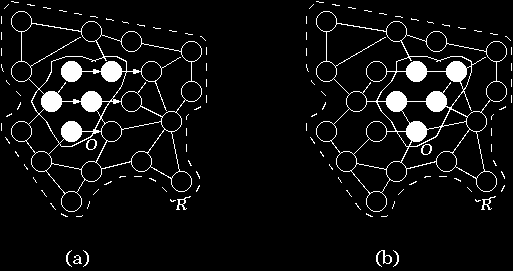
We choose a finite set of points from R. We place identical, synchronized computer processors at each of the points in this set, and connect some of these processors by bi-directional communication channels with delay time proportional to length. Our choices could produce the mesh-work of computer processors representing R} shown in Fig. (a). The circles (filled and unfilled) stand for the processors, and the solid lines for connections. Note that we did make some (possibly peculiar) choices to arrive at this particular mesh-works---we will refer to this matter below. Imagine that somehow each of the processors in this mesh-works is programmed to ``behave'' like the point of R it is placed on. So, we would have some processors programmed to behave like empty space (these are the unfilled ones in Fig. (a)), and others (the filled ones in Fig. (a)) programmed to behave as particles of O. Motion is represented, then, by the synchronized passage of messages, across direct communication channels, from one processor to another. Imagine that a processor that represents a particle of O instructs a directly connected processor in the direction of motion, to start representing that particle. In the example shown in Fig. (a) each neighboring processor in the direction of motion happens to be a constant length away from the particles of O, and, since all the processors in the mesh-works execute in synchrony (or in parallel), after one message passing, O would effectively have moved in the direction of motion. The arrows in Fig. (a) indicate the direction of motion of O. Fig. (b) shows the state of the mesh-works, as far as what each processor represents, after one message passing. Repeating this process over and over again, if it were possible, would result in the mesh-works simulating the uniform motion of O in R; moreover, the simulation time could come out linearly proportional to the actual time O would take to move in R.
Generalization of this description to higher dimensions should be
fairly clear, but it should also be clear that our choice of discrete points
and connections to represent R
is fairly higgledy-piggledy except for enabling us to cleanly
present the example, one step only
motion depicted in the above figure. About this one step motion example, the
reader may even suspect (correctly it turns out) that we
``cheated''. Early on in our project we
worried a lot about which set of points and interconnections
to use to represent a region and, for that choice,
how to deal with motions not so cleanly representable as the example in
the above figure. For example,
for a mesh-works of points arranged and connected in squares, but without
diagonal connections,
we had to deal with the question of how to
handle diagonal motion at roughly the same speed
as motion along the edge of a square. The example from
the above figure doesn't deal with
this and related problems, but our algorithms, discussed briefly below, do.